

Instructions for use for the IC-KP alignment device
Dear Customer,
You have received the alignment device from us. We kindly ask you to read the instructions carefully so that you are correctly informed about important information and safety instructions.
If you have any further questions, please do not hesitate to contact us.
Yours sincerely,
Team Kosow Prosthetics
Table of Contents
Instructions for use for the alignment device
1. Intended use
2. Use
2.1 Important information on the structure of the IC KP
2.2 Important information on constructing a prothesis
2.3 Positioning the prosthetic foot
2.4 Positioning the prosthetic knee joint
2.5 Positioning the prosthesis socket
2.6. Upkeeping and maintenance
3. Description of the individual components / accessories
3.1 Locking the prosthesis socket
3.2 Fixation of the knee joint
3.3 Footrest
3.4 Barometer/pressure reduction
3.5 Linear Rails
3.6 Ball joint
3.7 Drawer
1. Intended use
The IC-KP alignment device may only be used for the assembly of prostheses and operated by orthopaedic technicians only, because it requires special knowledge about lower extremity prosthetics. Due to the large number of setting options, the IC-KP enables precise compliance with the specifications that are prescribed for the various prosthesis components (see the instructions for use and assembly recommendations).
2. Use
2.1 Important information on the structure of the IC KP
To ensure sufficient stability, the IC-KP must be fixed locally. Therefore, please read the assembly instructions carefully, which have been given to you along with the instructions for use.
2.2 Important information on constructing a prosthesis
The assembly and adjustments may only be carried out by an orthopaedic technician, so that a prosthesis can be built optimally for the patient.
Determine the heel height using a heel height measuring device and also include this in the static structure. Position the prosthetic foot on the footrest so that the alignment criteria of the foot component are met.
Clamp the knee joint carefully and centred between the clamping jaws.
2.5 Positioning of the prosthesis socket
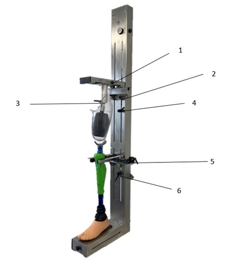
Hold the prosthesis socket under the bladder so that it can unfold inside the socket. Turn on the small black stopcock located on the left side to inflate the bladder. To bring the now fixed stem into position, you can use screwing 3 to change the rotation and tilt of the stem. Furthermore, you can use the slider on the right side to move the shaft frontally, dorsally, laterally and medially.
With the help of a laser plummet, you can position the prosthesis components in relation to one another in such a way that they meet the construction criteria of the components and the individual needs of the patient.
2.6. Upkeeping and maintenance
The device is maintenance-free if you keep it up and clean it yourself.
For maintenance, please note that the pressure reducer must not exceed 1.5 bar. In addition, the shut-off bladder should be checked regularly for wear.
3. Description of the individual components/accessories
3.1 Locking the prosthesis socket
For this purpose, a well-known technique from the sanitary language is used. The shut-off bladder can be inflated with the help of air pressure so that it is able to fix the shaft in its position.
Pressure reduction must not exceed 1.5 bar!
3.2 Knee joint fixation
The respective knee joint can be fixed in its intended position with the help of a centred linear guide (screw connection 5).
3.3 Footrest
It is a horizontal contact surface, which is used for the correct positioning of the foot part (note the necessary heel height).
3.4 Barometer/pressure reduction
Is used to check the pressure (1.5 bar) in the shut-off bladder.
3.5 Linear rails
3.5.1 Horizontal guidance
Serves to adjust the ML and AP position of the socket to the knee component (see screw connection 2 and 1)
3.5.2 Vertical guidance
Serves to adjust the distal and proximal position of the shaft and the centred linear guide (see crew connection 4 and 6)
3.6 Ball joint
Used to adjust the abduction, adduction, flexion and extension of the socket to suit the patient’s individual measurements and the specifications of the prosthesis components.
All settings of the linear rails and the ball guide can be adjusted by their respective
Screw connection can be both loosened and fixed.
3.7 Drawer
Can be used to store heel wedges, measuring tools and other necessary materials.